Step 15: And click on Show Shaded Material in Viewport to apply all change. Step 14: Click on the assign material to the selection button again to apply the change. Step 13: Press ok, After selecting Tiles. Step 12: Now, I will click on the No Map of Diffuse Map option tab and choose the tile option from an opened dialog box.


Step 11: Click on the assign material button again. Step 9: Click on assign material to the selection option. Click on the diffuse color tab and set the color. Step 7: Now, we will change the color of the plane from the Diffuse color option. Step 6: Choose the Architectural option here to applying material and press Ok. Step 5: Click on standard in the dialog box a new dialog box will be openly named with Material/Map Browser. Step 4: Now, I will press M from the keyboard for material editing of the plane for better reflection. Step 3: Now again, press the Alt +w button to see the normal view tab screens, and now I will work on perspective view and press Alt +W for fullscreen. Click anywhere on the top plane and drag the mouse pointer to draw the plane. Step 2: I will take the top viewport as a full screen to draw planes (Alt + W).

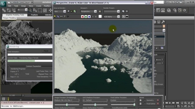
Rendering and Render Setup in 3D Max Softwareīelow are the steps showing the rendering setup option: We generally take its unit in inches because when we import any other model in or project, there will be no change in the imported model unit. Step 6: We have a system unit step option here. Step 5: And the other one is the US standard for setting units in Feet and Inches.


 0 kommentar(er)
